Product

- Home
- >
- Product
- >
- IEC/UL/TS Explosion-proof fittings
- >
- Non-Armoured Cable Gland-Union type UCC
-
-
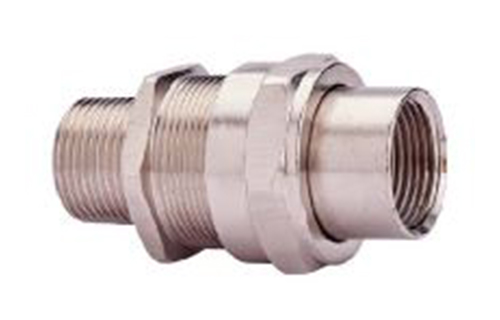
Non-Armoured Cable Gland-Union type UCC
ApplicationThe main function of the explosion-proof cable fixing connector is to use the cable into the distribution box or into the explosion-proof lighting device.
Specification
| Explosion proof execution | EX db IIC Gb,Ex eb IIC Gb,EX tb IIIC Db IP66 |
| Certificate issued by | TÜV Rheinland / TS mark |
| Material | Brass / Brass-Nickel Plating / Steel-Zinc Electroplated / Stain less Steel 304 / Stainless Steel 316 |
| Designation part number system | ||||
| 1 | UCC | 2 | 3 | 4 |
| Certification Unit | Name of fitting | Hub Size & Type | Thread Standard | Material |
| 1 Certification Unit / Code | |||||
| International Electrotechnical Commission / IEC | |||||
| 2 Hub Size / Code lnch | |||||||||||
| Hub Size | 1/2"A | 1/2"B | 3/4" | 1 | 1-1/4" | 1-1/2" | 2"A | 2"B | 2-1/2"A | 2-1/2"B | 3" |
| Code | 050A | 050B | 075 | 100 | 125 | 150 | 200A | 200B | 250A | 250B | 300 |
| Metric | |||||||||||
| Hub Size | M20A | M20B | M25 | M32 | M40 | M50A | M50B | M63A | M63B | M75A | M75B |
| Code | 20A | 20B | 25 | 32 | 40 | 50A | 50B | 63A | 63B | 75A | 75B |
| 3 Thread Standards / Code | |||||
| Thread Standards | Code | ||||
| NPT | N | ||||
| Metric Fine Thread | M | ||||
| 4 Material / Finish / Code | |||||
| Material | Code | ||||
| Brass | B | ||||
| SUS304 | S4 | ||||
| Brass / Nickel Plating | BN | ||||
| SUS316 | S6 | ||||
| Steel / Zinc Electroplated | E | ||||
| Example | ||||
| IEC | UCC | 075 | N | BN |
| Certification Unit | Name of fitting | Hub Size & Type | Thread Standard | Material |
| IEC | Non-Armoured Cable Gland-Union type | 3/4" | NPT | Brass / Nickel Plating |
| IEC | UCC | 25 | M | S4 |
| Certification Unit | Name of fitting | Hub Size & Type | Thread Standard | Material |
| IEC | Non-Armoured Cable Gland-Union type | M25 | Metric Fine Thread | SUS304 |
Introduction
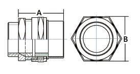
| Hub Size | Dimensions (mm) | 電纜外徑 | |||
| Metric | Inch | A | B | Overall Cable Diameter | |
| M20A | 1/2"A | 52 | 32 | 4~8.9 | |
| M20B | 1/2"B | 52 | 32 | 9~13.9 | |
| M25 | 3/4 | 57 | 38 | 14~19.9 | |
| M32 | 1" | 57 | 44 | 20~25.3 | |
| M40 | 1-1/4" | 59 | 54 | 25~31.8 | |
| M50A | 1-1/2" | 61 | 60 | 31~37.8 | |
| M50B | 2"A | 69 | 76 | 38~44.8 | |
| M63A | 2"B | 69 | 76 | 42~48.8 | |
| M63B | 2-1/2"A | 73 | 92 | 49~55.8 | |
| M75A | 2-1/2"B | 73 | 92 | 55~61.7 | |
| M75B | 3" | 78 | 106 | 61.5~68.7 | |
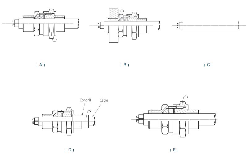
| Instruction of Non-Armoured Cable Gland | ||||
| A |
There is no need to dismantle the cable gland prior to installation.
Simply slacken the Seal Nut (3) to relax the Seal Ring (2) |
|||
| B | Fit the gland into the equipment and fully tighten the Entry Item (1). | |||
| C | Determine the conductor length required to suit the installation and prepare the cable accordingly, removing part of the outer sheath where required to reveal the insulated conductors. |
|||
| D | Attach the conduit to the Conduit Coupler (4) and fully tighten. | |||
| E | Pass the cable through the gland to the needed position, then tighten the Seal Nut(3) and let the Conduit Coupler(4) contact the Seal Ring(2). Fix the Entry Item(1) with wrench and keep it from turning. Use another wrench and let the Seal Nut(3) tighten up the Seal Ring(2) until the cable is completely sealed. |
|||
Product Consultation