Product

- Home
- >
- Product
- >
- IEC/UL/TS Explosion-proof fittings
- >
- Armoured Cable Gland ACG
-
-
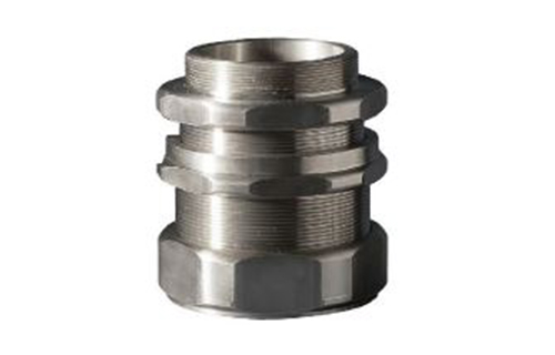
Armoured Cable Gland ACG
ApplicationThe main function of the explosion-proof cable fixing connector is to use the cable into the distribution box or into the explosion-proof lighting device.
Specification
| Explosion proof execution | EX db IIC Gb,Ex eb IIC Gb,EX t b IIIC Db IP66 |
| Certificate issued by | TÜV Rheinland / TS mark. |
| Material | Brass / Brass-Nickel Plating / Steel-Zinc Electroplated / Stainless Steel 304 / Stainless Steel 316 |
| Designation part number system | ||||
| 1 | ACG | 2 | 3 | 4 |
| Certification Unit | Name of fitting | Hub Size & Type | Thread Standard | Material |
| 1 Certification Unit / Code | |||||
| International Electrotechnical Commission / IEC | |||||
| 2 Hub Size / Code lnch | |||||||||||
| Hub Size | 1/2" | 3/4"A | 3/4"B | 1 | 1-1/4" | 1-1/2" | 2"A | 2"B | 2-1/2"A | 2-1/2"B | 3" |
| Code | 050 | 075A | 075B | 100 | 125 | 150 | 200A | 200B | 250A | 250B | 300 |
| Metric | |||||||||||
| Hub Size | M20 | M25A | M25B | M32 | M40 | M50A | M50B | M63A | M63B | M75A | M75B |
| Code | 20 | 25A | 25B | 32 | 40 | 50A | 50B | 63A | 63B | 75A | 75B |
| 3 Thread Standards / Code | |||||
| Thread Standards | Code | ||||
| Metric Fine Thread | M | ||||
| NPT | N | ||||
| 4 Material / Finish / Code | |||||
| Material | Code | ||||
| Brass | B | ||||
| SUS304 | S4 | ||||
| Brass / Nickel Plating | BN | ||||
| SUS316 | S6 | ||||
| Steel / Zinc Electroplated | E | ||||
| Example | |||||
| IEC | ACG | 25A | M | S4 | |
| Certification Unit | Name of fitting | Hub Size & Type | Thread Standard | Material | |
| IEC |
Armoured Cable Gland
|
M25A(TYPE) |
|
SUS304 | |
| IEC | ACG | 250A | N | BN |
| Certification Unit 認證單位 |
Name of fitting 產品代碼 |
Hub Size & Type 尺寸和型式 |
Thread Standard 螺紋 |
Material 材質 |
| IEC | Armoured Cable Gland | 2-1/2"A(TYPE) | NPT | Brass / Nickel Plating |
Introduction
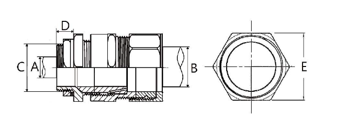
| Available Entry Thread | Cable Bedding Diameter | Overall Cable Diameter | E | Armour Ranger | ||||||
| C | A | B | Min. | Max. | ||||||
| Metric(P1.5) | Inch(NPT) | Min. | Max. | Min. | Max. | |||||
| M20 | 1/2" | 6.5 | 13.9 | 12.5 | 20.9 | 36 | 0.8 | 1.25 | ||
| M25A | 3/4"A | 11.0 | 19.9 | 14.0 | 22.0 | 40 | 1.25 | 1.6 | ||
| M25B | 3/4"B | 11.0 | 19.9 | 18.2 | 26.2 | 40 | 1.25 | 1.6 | ||
| M32 | 1" | 17.0 | 26.4 | 23.7 | 33.9 | 48 | 1.6 | 2.0 | ||
| M40 | 1-1/4" | 22.0 | 31.8 | 27.9 | 40.4 | 57 | 1.6 | 2.0 | ||
| M50A | 1-1/2" | 29.5 | 37.8 | 35.2 | 46.7 | 64 | 2.0 | 2.5 | ||
| M50B | 2"A | 35.0 | 45.8 | 40.4 | 53.1 | 71 | 2.0 | 2.5 | ||
| M63A | 2"B | 40.0 | 49.8 | 45.6 | 59.4 | 76 | 2.0 | 2.5 | ||
| M63B | 2-1/2"A | 47.0 | 56.7 | 54.6 | 65.9 | 82 | 2.0 | 2.5 | ||
| M75A | 2-1/2"B | 52.0 | 61.7 | 59.0 | 72.1 | 90 | 2.0 | 2.5 | ||
| M75B | 3" | 59.0 | 68.7 | 66.7 | 78.5 | 98 | 2.5 | 3.0 | ||
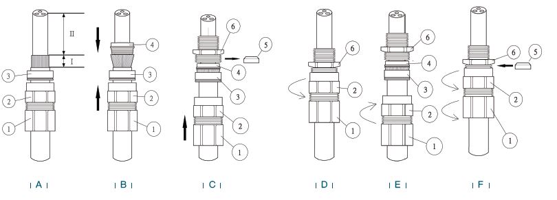
| Instruction of Amoured Cable Gland | |
| A |
Strip Cable to suit equipment as shown above and expose the armour 'I'.
'I' = 20mm for cable gland sizes 1/2" (M20) to 1" (M32) 'I' = 25mm for cable gland sizes 1-1/4" (M40) to 2" (M63) 'I' = 30mm for cable gland sizes 2-1/2" (M63) to 3" (M75) 'II' = to suit equipment. |
| B | Push the cable through the armour spigot "4". Spread armour over the armour spigot "4" until the end of the armour is up against the shoulder of the armour cone. Position the armour clamping ring "3". |
| C | Remove the inner seal "5" from the entry "6". Place the entry "6" over the armour spigot "4". Move the sub-assembly "1"and "2" up to meet the entry "6". Note: If the equipment has a threaded entry, it may be advisable to screw the entry component into the equipment to prevent twisting of the cable after step D. |
| D | Unless already screwed into the equipment hold the entry "6" in position with a spanner/wrench to prevent rotation. Hand tighten the middle nut "2" to the entry "6" and turn a further half to one full turn with a spanner/wrench. IMPORTANT: Support the cable to prevent it from twisting. To ease wiring inside the enclosure, it may be beneficial to strip the inner sheath of the cable as shown above. |
| E | Unscrew the middle nut "2" and visually inspect that the armour has been successfully clamped between the armour spigot "4" and the armour clamping ring "3". If armour not clamped, repeat assembly. |
| F | Remove entry "6" and refit inner seal "5", replace entry "6" and reassemble middle nut "2" onto the entry component "6". Tighten u p the middle nut "2" by hand then using a wrench/spanner a further 1 to 2 turns until fully tight. Tighten the backnut "1" to form a se al around the cable, then tighten a further full turn using a wrench/span ner. Ensure that the middle nut "2" does not rotate when tightening the backnut "1". Ensure that the deluge seal is pulled down into position. |
Product Consultation