Product

- Home
- >
- Product
- >
- High Pressure Tubes & Fittings High Pressure Pipes & Fittings
- >
- HP-CAP CAP
-
-
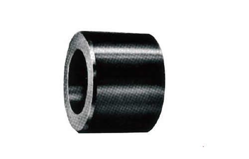
HP-CAP CAP
Specification
| Designation part number system | |||||
| HP | 1 | 2 | 3 | 4 | 5 |
| Name of Fitting | Pressure & NIP thickess | Hub Size | Port type: Thread End&Socket-Weld End | Material | |
| 1 Name of Fitting | |||||
| Name of fittings | Code | ||||
| Reference Cat.NO. | |||||
| 2 Pressure & NIP thickess | |||||
| Pressure | Code | ||||
| Thread End: 2000, 3000, 6000 LBS | 2, 3, 6 | ||||
| Socket-Weld End: 3000, 6000, 9000 LBS | 3, 6, 9 | ||||
| NIP Pipe thickness | Code | ||||
| SCH40, SCH80, SCH160, XXS | S40, S80, S160, XXS | ||||
| 3 Hub Size / Code | ||||||||||||
| Hub Size | 1/8" | 1/4" | 3/8" | 1/2" | 3/4" | 1" | 1-1/4" | 1-1/2" | 2" | 2-1/2" | 3" | 4" |
| Code | 01 | 02 | 03 | 04 | 06 | 1 | 12 | 15 | 2 | 25 | 3 | 4 |
| 4 Port type: Thread End&Socket-Weld End | |||||
| Port Type | Code | ||||
| Thread standard: BSPT | P | ||||
| Thread standard: NPT | N | ||||
| Socket-Weld End | SW | ||||
| 5 Material / Code | |||||
| Material | Code | ||||
| A105, A106 | A (Anti-rust Oil Coating ) | ||||
| A105, A106 | E (Zinc Electroplated ) | ||||
| A105, A106 | H (Hot Dip Galvanized ) | ||||
| A182 F304 (304L) | S4 (304#) | ||||
| A182 F316 (316L) | S6 (316#) | ||||
| Optional Material SPEC: A350 LF2, A403, A234, A182 (F304H, F317L, F321, F5, F9, F11, F22, F44, F51, F53, F91) |
|||||
| DIM.SPEC. : ASME B16.11 | MSS SP-79,83,95,97,BS3799 | ||||
| Example | |||||
| HP | T | 2 | 04 | N | A |
| Name of Fitting | Pressure & NIP thickness | Hub Size | Port type: Thread End&Socket-Weld End | Material | |
| Tee | 2000 LBS | 1/2" | NPT | A105 | |
| HP | NIP | S80 | 1 | N | 3L | S6 |
| Name of Fitting | Pressure & NIP thickness | Hub Size | Port type: Thread End&Socket-Weld End | NIP Length | Material | |
| Nipple | SCH 80 | 1" | NPT | 3"L(75mm) | A182 F316 | |
| HP | HBU | 3 | 1M | N | 06F | N | S6 |
| Name of Fitting | Pressure & NIP thickness | Hub Size(Male) | Port type: Thread End&Socket-Weld End | Hub Size(Female) | Port type: Thread End&Socket-Weld End | Material | |
| Bushing | 3000 LBS | Male | NPT | Female | NPT | A182 F316 | |
Introduction
Socket-Welding Fittings.
ASME B16.11-2016 (Revision of ASME B16.11-2011)
ASME B16.11-2016 (Revision of ASME B16.11-2011)
|
·Dimensions in Millimeters
|
||||||||||||||||||
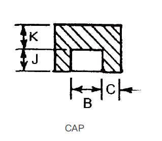
| DN | Nom. Pipe Size |
Socket Bore Dia.(2) B |
Bore Diameter of ittings(2) D |
Socket Wall Thickness(1) C | Body Wall Thickness G |
Depth of Socket Min J |
||||||||||||
| Class Designation | ||||||||||||||||||
| Class Designation | 3000 | 6000 | 9000 | Class Designation | ||||||||||||||
| 3000 | 6000 | 9000 | Aev. | Min. | Aev. | Min. | Aev. | Min. | 3000 | 6000 | 9000 | |||||||
| Min. | Min. | Min. | ||||||||||||||||
| 6 | 1/8 | 11.2 10.8 |
7.6 6.1 |
4.8 3.2 |
3.18 | 3.18 | 3.96 | 3.43 | 2.41 | 3.15 | 9.5 | |||||||
| 8 | 1/4 | 14.6 14.2 |
10.0 8.5 |
7.1 5.6 |
3.78 | 3.30 | 4.60 | 4.01 | 3.02 | 3.68 | 9.5 | |||||||
| 10 | 3/8 | 18.0 17.6 |
13.3 11.8 |
9.9 8.4 |
4.01 | 3.50 | 5.03 | 4.37 | 3.20 | 4.01 | 9.5 | |||||||
| 15 | 1/2 | 22.2 21.8 |
16.6 15.0 |
12.5 11.0 |
7.2 5.6 |
4.67 | 4.09 | 5.97 | 5.18 | 9.35 | 8.18 | 3.73 | 4.78 | 7.47 | 9.5 | |||
| 20 | 3/4 | 27.6 27.2 |
21.7 20.2 |
16.3 14.8 |
11.8 10.3 |
4.90 | 4.27 | 6.96 | 6.04 | 9.78 | 8.56 | 3.9 | 5.56 | 7.8 | 12.5 | |||
| 25 | 1 | 34.3 33.9 |
27.4 25.9 |
21.5 19.9 |
16.0 14.4 |
5.69 | 4.98 | 7.92 | 6.93 | 11.38 | 9.96 | 4.55 | 6.35 | 9.09 | 12.5 | |||
| 32 | 1-1/4 | 43.1 42.7 |
35.8 34.3 |
30.2 28.7 |
23.5 22.0 |
6.07 | 5.28 | 7.92 | 6.93 | 12.14 | 10.62 | 4.85 | 6.35 | 9.70 | 12.5 | |||
| 40 | 1-1/2 | 49.2 48.8 |
41.6 40.1 |
34.7 33.2 |
28.7 27.2 |
6.35 | 5.54 | 8.92 | 7.60 | 12.7 | 11.12 | 5.08 | 7.14 | 10.15 | 12.5 | |||
| 50 | 2 | 61.7 61.2 |
53.3 51.7 |
43.6 42.1 |
38.9 37.4 |
6.93 | 6.04 | 10.92 | 9.50 | 13.84 | 12.12 | 5.54 | 8.74 | 11.07 | 16.0 | |||
| 65 | 2-1/2 | 74.4 73.9 |
64.2 61.2 |
8.76 | 7.67 | 7.01 | 16.0 | |||||||||||
| 80 | 3 | 90.3 89.8 |
79.4 76.4 |
9.52 | 8.30 | 7.62 | 16.0 | |||||||||||
| 100 | 4 | 115.7 115.2 |
103.8 100.7 |
10.69 | 9.35 | 8.56 | 19.0 | |||||||||||
| NOTE. ·Average of Socket Wall Thickness around periphery shall be no l ess than listed values. The minimum values are permitted in localized areas. ·Upper and lower values for each size are the respective maximum and minimum dimensions. |
||||||||||||||||||
|
·Dimensions in Millimeters
|
||||||||||||||||||
| DN | Nom. Pipe Size |
Center to Bottom of Socket-A | Laying Lengths | Tolerances | End Wall Thickness K Min |
|||||||||||||
| 90º Elbows Tees, Crosses |
45º Elbows | Couplings E |
Half Couplings E |
A | E | F | ||||||||||||
| Class Designation | Class Designation | |||||||||||||||||
| 3000 | 6000 | 9000 | 3000 | 6000 | 9000 | 3000 | 6000 | 9000 | ||||||||||
| 6 | 1/8 | 11.0 | 11.0 | 8.0 | 8.0 | 6.5 | 16.0 | 1.0 | 1.5 | 1.0 | 4.8 | 6.4 | ||||||
| 8 | 1/4 | 11.0 | 13.5 | 8.0 | 8.0 | 6.5 | 16.0 | 1.0 | 1.5 | 1.0 | 4.8 | 6.4 | ||||||
| 10 | 3/8 | 13.5 | 15.5 | 8.0 | 11.0 | 6.5 | 17.5 | 1.5 | 3.0 | 1.5 | 4.8 | 6.4 | ||||||
| 15 | 1/2 | 15.5 | 19.0 | 25.5 | 11.0 | 13.0 | 15.5 | 9.5 | 22.5 | 1.5 | 3.0 | 1.5 | 6.4 | 7.9 | 11.2 | |||
| 20 | 3/4 | 19.0 | 22.5 | 28.5 | 13.0 | 14.0 | 19.0 | 9.5 | 24.0 | 1.5 | 3.0 | 1.5 | 6.4 | 7.9 | 12.7 | |||
| 25 | 1 | 22.5 | 27.0 | 32.0 | 14.0 | 17.5 | 20.5 | 12.5 | 28.5 | 2.0 | 4.0 | 2.0 | 9.6 | 11.2 | 14.2 | |||
| 32 | 1-1/4 | 27.0 | 32.0 | 35.0 | 17.5 | 20.5 | 22.5 | 12.5 | 30.0 | 2.0 | 4.0 | 2.0 | 9.6 | 11.2 | 14.2 | |||
| 40 | 1-1/2 | 32.0 | 38.0 | 38.0 | 20.5 | 22.5 | 25.5 | 12.5 | 32.0 | 2.0 | 4.0 | 2.0 | 11.2 | 12.7 | 15.7 | |||
| 50 | 2 | 38.0 | 41.0 | 54.0 | 25.5 | 28.5 | 28.5 | 19.0 | 41.0 | 2.0 | 4.0 | 2.0 | 12.7 | 15.7 | 19.0 | |||
| 65 | 2-1/2 | 41.0 | 28.5 | 19.0 | 43.0 | 2.5 | 5.0 | 2.5 | 15.7 | 19.0 | ||||||||
| 80 | 3 | 57.0 | 32.0 | 19.0 | 44.5 | 2.5 | 5.0 | 2.5 | 19.0 | 22.4 | ||||||||
| 100 | 4 | 66.5 | 410 | 19.0 | 48.0 | 2.5 | 5.0 | 2.5 | 22.4 | 28.4 | ||||||||
| NOTE. ·Average of Socket Wall Thickness around periphery shall be no l ess than listed values. The minimum values are permitted in localized areas. ·Upper and lower values for each size are the respective maximum and minimum dimensions. |
||||||||||||||||||
Product Consultation