Product

- Home
- >
- Product
- >
- High Pressure Tubes & Fittings High Pressure Pipes & Fittings
- >
- HP-BPLUG BULL PLUG
-
-
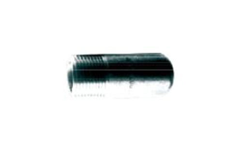
HP-BPLUG BULL PLUG
Specification
| Designation part number system | |||||
| HP | 1 | 2 | 3 | 4 | 5 |
| Name of Fitting | Pressure & NIP thickess | Hub Size | Port type: Thread End&Socket-Weld End | Material | |
| 1 Name of Fitting | |||||
| Name of fittings | Code | ||||
| Reference Cat.NO. | |||||
| 2 Pressure & NIP thickess | |||||
| Pressure | Code | ||||
| Thread End: 2000, 3000, 6000 LBS | 2, 3, 6 | ||||
| Socket-Weld End: 3000, 6000, 9000 LBS | 3, 6, 9 | ||||
| NIP Pipe thickness | Code | ||||
| SCH40, SCH80, SCH160, XXS | S40, S80, S160, XXS | ||||
| 3 Hub Size / Code | ||||||||||||
| Hub Size | 1/8" | 1/4" | 3/8" | 1/2" | 3/4" | 1" | 1-1/4" | 1-1/2" | 2" | 2-1/2" | 3" | 4" |
| Code | 01 | 02 | 03 | 04 | 06 | 1 | 12 | 15 | 2 | 25 | 3 | 4 |
| 4 Port type: Thread End&Socket-Weld End | |||||
| Port Type | Code | ||||
| Thread standard: BSPT | P | ||||
| Thread standard: NPT | N | ||||
| Socket-Weld End | SW | ||||
| 5 Material / Code | |||||
| Material | Code | ||||
| A105, A106 | A (Anti-rust Oil Coating ) | ||||
| A105, A106 | E (Zinc Electroplated ) | ||||
| A105, A106 | H (Hot Dip Galvanized ) | ||||
| A182 F304 (304L) | S4 (304#) | ||||
| A182 F316 (316L) | S6 (316#) | ||||
| Optional Material SPEC: A350 LF2, A403, A234, A182 (F304H, F317L, F321, F5, F9, F11, F22, F44, F51, F53, F91) |
|||||
| DIM.SPEC. : ASME B16.11 | MSS SP-79,83,95,97,BS3799 | ||||
| Example | |||||
| HP | T | 2 | 04 | N | A |
| Name of Fitting | Pressure & NIP thickness | Hub Size | Port type: Thread End&Socket-Weld End | Material | |
| Tee | 2000 LBS | 1/2" | NPT | A105 | |
| HP | NIP | S80 | 1 | N | 3L | S6 |
| Name of Fitting | Pressure & NIP thickness | Hub Size | Port type: Thread End&Socket-Weld End | NIP Length | Material | |
| Nipple | SCH 80 | 1" | NPT | 3"L(75mm) | A182 F316 | |
| HP | HBU | 3 | 1M | N | 06F | N | S6 |
| Name of Fitting | Pressure & NIP thickness | Hub Size(Male) | Port type: Thread End&Socket-Weld End | Hub Size(Female) | Port type: Thread End&Socket-Weld End | Material | |
| Bushing | 3000 LBS | Male | NPT | Female | NPT | A182 F316 | |
Introduction
BULL PLUGS.
MSS SP-79-2014
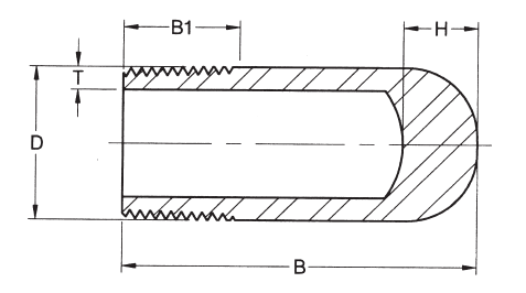
MSS SP-79-2014
| Size (in) |
D | B | B1 | T min | H | |||
| Sch40 (STD) |
Sch80 (XS) |
Sch160 | XXS | |||||
| 1/8 | 10.3 | 34 | 9.5 | 1.75 | 2.41 | 3.20 | 4.8 | 14 |
| 1/4 | 13.7 | 34 | 11.0 | 2.24 | 3.02 | 3.70 | 6.1 | 14 |
| 3/8 | 17.1 | 57 | 12.5 | 2.31 | 3.20 | 4.00 | 6.4 | 14 |
| 1/2 | 21.3 | 64 | 14.5 | 2.77 | 3.73 | 4.78 | 7.47 | 14 |
| 3/4 | 26.7 | 70 | 16.0 | 2.87 | 3.91 | 5.56 | 7.82 | 18 |
| 1 | 33.4 | 76 | 19.0 | 3.38 | 4.56 | 6.35 | 9.09 | 18 |
| 1-1/4 | 42.2 | 83 | 20.5 | 3.56 | 4.85 | 6.35 | 9.70 | 18 |
| 1-1/2 | 48.3 | 89 | 20.5 | 3.68 | 5.05 | 7.14 | 10.15 | 18 |
| 2 | 60.3 | 102 | 22.0 | 3.91 | 5.54 | 8.74 | 11.07 | 20 |
| 2-1/2 | 73.0 | 127 | 27.0 | 5.16 | 7.01 | 9.53 | 14.02 | 20 |
| 3 | 88.9 | 152 | 28.5 | 5.49 | 7.60 | 11.13 | 15.24 | 20 |
| 4 | 114.3 | 178 | 32.0 | 6.35 | 8.08 | 13.49 | 17.12 | 20 |
|
·Thread in Accordance with AME B1.20.1 ·Wall Thickness (T Min.) in Accordance with ASME B36. 10 M.
|
||||||||
| DIMENSIONAL TOLERANCES OF FORGED SOCKET WELDING FITTING. | ||||||
| ASME B16.11-2001 | ||||||
| ltem | Type of pipe fitting |
Nominal diameter | ||||
| A | 6 t 8 | 10 to 20 | 25 to 50 | 65 to 100 | ||
| B | 1/8 to 1/4 | 3/8 to 3/4 | 1 to 2 | 2-1/2 to 4 | ||
| Bore diameter of socket (B) | All tupes of pipe fittings |
+0.3 -0 |
+0.4 -0 |
|||
| Bore diameter of fitting (D) | ±0.4 | ±0.8 | ||||
| Centricity of bore (X) | ±0.8 | |||||
| Cion cadence of axes (Y) | 1.5/300 Max | |||||
| Center to bottom of socket (A) | 45,90D Elbow, Tee | ±0.8 | ±1.5 | ±2 | ±2.5 | |
| Center to bottom of socket (E) | Full coupling | ±1.5 | ±3 | ±4 | ±5 | |
| Bottom of socket to oppdsite face (F) | Half coupling | ±0.8 | ±1.5 | ±2 | ±2.5 | |
|
·Unit:mm
|
||||||
Product Consultation